Fluid flow in cleaning of closed processes
- Like
- Digg
- Del
- Tumblr
- VKontakte
- Buffer
- Love This
- Odnoklassniki
- Meneame
- Blogger
- Amazon
- Yahoo Mail
- Gmail
- AOL
- Newsvine
- HackerNews
- Evernote
- MySpace
- Mail.ru
- Viadeo
- Line
- Comments
- Yummly
- SMS
- Viber
- Telegram
- Subscribe
- Skype
- Facebook Messenger
- Kakao
- LiveJournal
- Yammer
- Edgar
- Fintel
- Mix
- Instapaper
- Copy Link
Posted: 9 March 2006 | Assistant Professor Bo Boye Busk Jensen and Associate Professor Alan Friis, Food Biotechnology and Engineering, BioCentrum-DTU | No comments yet
The efficiency of Cleaning-In-Place (CIP) procedures greatly depends on fluid flow (i.e. the motion of detergent and rinsing water). Thorough understanding of the physical action of fluid flow during cleaning allows for redesign of equipment and design of CIP procedures with respect to optimal cleaning characteristics. This article discusses the importance of fluid flow as an aspect of the cleaning processes. Computational Fluid Dynamics (CFD) is applied for prediction of areas inside closed process equipment, which are potentially difficult to clean. Finally, some commonly encountered questions on flow conditions during cleaning are discussed based on CFD results.
The efficiency of Cleaning-In-Place (CIP) procedures greatly depends on fluid flow (i.e. the motion of detergent and rinsing water). Thorough understanding of the physical action of fluid flow during cleaning allows for redesign of equipment and design of CIP procedures with respect to optimal cleaning characteristics. This article discusses the importance of fluid flow as an aspect of the cleaning processes. Computational Fluid Dynamics (CFD) is applied for prediction of areas inside closed process equipment, which are potentially difficult to clean. Finally, some commonly encountered questions on flow conditions during cleaning are discussed based on CFD results.
The efficiency of Cleaning-In-Place (CIP) procedures greatly depends on fluid flow (i.e. the motion of detergent and rinsing water). Thorough understanding of the physical action of fluid flow during cleaning allows for redesign of equipment and design of CIP procedures with respect to optimal cleaning characteristics. This article discusses the importance of fluid flow as an aspect of the cleaning processes. Computational Fluid Dynamics (CFD) is applied for prediction of areas inside closed process equipment, which are potentially difficult to clean. Finally, some commonly encountered questions on flow conditions during cleaning are discussed based on CFD results.
Proper cleaning and good hygienic maintenance of processing equipment is a prerequisite for production of safe and high quality products in such diverse areas as: food processing, biotechnology, pharmaceutical processing, paper production, cosmetic production, etc. Additionally, the efficiency of cleaning has economical aspects due to reduced cleaning time, reduced consumption of cleaning agents and effluent reduction. The ever increasing public awareness of microbial contamination of food also actualises overall optimisation of the hygienic state along the entire production chain. A prerequisite for easy and effective cleaning is to use processes and equipment designed with respect to optimal cleaning characteristics.
A good hygienic state of a production line can be achieved by designing and constructing in accordance with guidelines from, for example, the European Hygienic Engineering and Design Group (EHEDG). Generally, such guidelines provide excellent basic rules for the design and construction of equipment and process lines intended for producing safe and high quality products. However, detailed information on good hygienic design in problem areas may be needed to increase the level of hygienic design still further. Hence, tools for evaluating the effect of local phenomena on cleaning characteristics in order to yield in-depth knowledge of why guidelines read as they do, will be beneficial. One area of potential development is the influence of flow patterns on cleaning efficiency in closed equipment (Friis et al., 2002).
The focus of this article is on equipment in closed process systems where validation of cleaning procedures is difficult (e.g. valves, pumps and dead-ends). Hence, alternative methods for validation, or at least prediction, of the efficiency of cleaning procedures are desired. A recent Ph.D. project at BioCentrum-DTU applied numerical models for prediction of flow (Computational Fluid Dynamics (CFD)) to predict areas difficult to clean in closed processing systems (Jensen, 2004). This paper presents an example of applying CFD for validation of cleanability seen in relation to the EHEDG cleaning test (Anon, 2000).
Fluid flow and cleaning
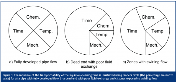
Applying CFD for quantitative prediction of cleaning efficiency is only possible when the influences of flow on cleaning of surfaces are known in advance. However, qualitative studies can be performed with less detailed knowledge. Cleaning can be looked upon as the energy needed to remove soil from a surface. The energy necessary to remove soil from a surface can be divided into four different contributions (see Figure 1a – based on Sinner, 1960); one from detergents (chemistry), one from temperature (heat), one from cleaning time (contact time between soil and liquid at different concentrations or temperatures) and one from mechanical forces (shear stress). During the application of cleaning chemicals and heat, bonds between soil and surface are loosened, while mechanical forces remove soil from the surface. The longer the contact time between soil, chemicals and heat the weaker the attachment and, as a consequence, the lower the forces needed to remove the soil from the surface. On the contrary, if the concentration of chemicals, the temperature of the liquid or the mechanical force is too low, the cleaning time must be increased in order to remove the same amount of soil from the surface (Figure 1b).
The action of fluid flow is important
Considering cleaning of closed processing equipment, fluid flow has an influence on all four components in Sinners circle, either directly or indirectly. The mechanical force is directly connected to the flow by the wall shear stress. In a closed process the sole practical method of applying a force is through flowing fluid. Flow parallel to a surface generates a force (a wall shear stress) on the surface (or the soil on the surface). Indirectly, fluid flow (i.e. the flow patterns) influences transport of cleaning liquid containing detergent (chemistry) and heat (mass and heat transfer). In a straight pipe fluid is continuously supplied to the edges of the boundary layer mainly due to convection. Through the boundary layer (a thin layer of fluid near the wall) detergent and heat is transported by diffusion driven by a gradient. There will always be a dominant flow on a global level which moves liquid through a piece of equipment. However, some geometrical shapes create locally reverse flows, recirculation zones (static and dynamic) and other complex flow patterns. Areas with static recirculation zones can be pictured as relatively isolated from the bulk flow. The exchange of detergent and heat between such zones and the bulk flow is lower than in the bulk flow itself. As a consequence the contact time between soil and cleaning liquid at the intended concentration and temperature is reduced (the gradient is smaller than in a straight pipe). Due to lower temperature and lower degree of detergent renewal it takes more time to loosen bonds between soil and surface to an extent where the mechanical force can remove the soil from the surface (Figure 1b). In addition, forces are low in the recirculation zone. Another type of recirculation zone can be found in some geometrical shapes. These are called swirling flows (helical shaped flow structures). The swirling motion enhances fluid exchange, i.e. the cleaning efficiency is improved compared to straight pipe flow (Figure 1c) (Jensen et al. 2005a). An additional effect of the moving liquid is that the fluid transports detached soil away from the surface and out of the processing line so reattachment is avoided.
Identifying areas potentially difficult to clean
The influence of fluid flow on cleaning is not limited to the mechanical force provided by the flow alone. Based on knowledge of the combined effect of wall shear stress and mass and heat-transfer (fluid exchange) the influence of fluid flow on cleaning can be predicted. Using CFD simulations it is possible to predict areas difficult to clean. These areas coincide well with areas identified as poorly cleanable using the EHEDG test (the test methods is described by Anon, 2000). Hence it is possible to identify flow patterns that promote or prohibit good cleaning of surfaces in closed processing equipment. Of course this can also be applied to evaluate new CIP procedures. Ideally, general combinations of wall shear stress magnitude and fluid exchange magnitude should be set-up (Table 1) in order to set the basis for evaluating hygienic design using CFD.
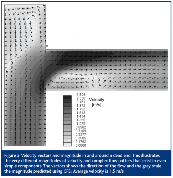
The CFD approach can be used to predict wall shear stresses and fluid exchange based on predicted velocity fields. Ideally, the velocity fields should be validated using e.g. Laser Doppler Anemometry. Once validated the CFD simulations can provide the necessary information on the important flow parameters with respect to cleaning (flow patterns, wall shear stress, fluid exchange between bulk and near-wall regions and fluctuations of wall shear stress (Jensen et al., 2005b)). In particular, transient simulations (including the evolution of flow over time) of flow in processing equipment with focus on flow in the near-wall region makes it possible to estimate the location of areas where cleaning problems are likely to occur first, second and so on (example given in Figure 3). Furthermore, alternative flow conditions during CIP and the effect on problem areas when incorporating design changes in a component can be compared using CFD simulations.
Do higher average velocities provide better cleaning?
Let us try to answer an often posed question amongst food producers, manufactures of processing equipment and people designing CIP systems using CFD simulations. Will increased average flow velocity during cleaning give better cleaning efficiencies? Intuitively, a higher average velocity is expected to improve cleaning characteristics, since shear stresses will increase with velocity raised to the power of 1.75 in fully developed pipe flow. Furthermore, the size and position of recirculation zones should intuitively change. Ideally, this should reduce the size of the areas where the mechanical force is too limited to remove the soil. The magnitude of the mechanical force will increase with velocity; however, the size, type and location of recirculation zones do not change if the Reynolds number is above 30,000, which is typically the case during cleaning operations. Generally, higher average velocities yield improved cleaning efficiency in areas where the cleaning is already good at lower velocities. However, areas with very low initial wall shear stresses will only be exposed to slightly higher wall shear stresses, as these areas are likely to be located in recirculation zones.
Should CIP velocity be 1.5 m/s?
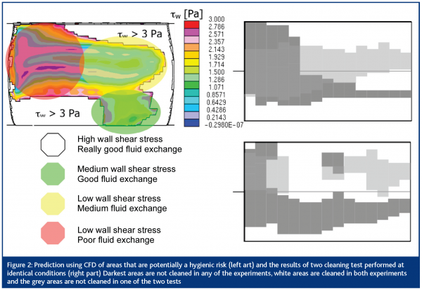
Guidelines and publications on cleaning and hygiene recommend an average flow velocity during cleaning of at least 1.5 m/s to ensure sufficient cleaning during CIP. This is a good rule of thumb used with success in the food industry. An average velocity above 1.5 m/s guarantees turbulent flow in straight pipes (d > 0.01 m). The turbulent nature of the flow provides good transport of mass and heat from the bulk flow to the near-wall region. Additionally, an average velocity above 1.5 m/s provides a thin boundary layer at the wall, which yields good transport of mass and heat from the outside of the boundary layer to the soil on the surface. There are proofs stating that the average velocity should not be lower than 1.5 m/s in straight pipes (Timperley et al. 1980). However, when optimising the geometrical design an average velocity is not so important. It is the local flow conditions – the flow pattern – that deserves attention. Hence an average velocity of 1.5 m/s can lead to areas of both very low and very high velocity, even in very simple components, such as valves, dead-ends, pipe bends etc. (Figure 2). Therefore, in order to control the cleanability the designer must look for local values of wall shear stress and fluid exchange, preferably using a CFD programme.
Conclusion and perspectives
Exploiting the strength of CFD simulations makes it possible to obtain an insight into the motion of liquid during cleaning of closed processing equipment. This provides a golden opportunity to test existing knowledge of the influence of flow on cleaning and also to gain new knowledge in this area. Wall shear stress has been believed to be the key parameter in evaluating cleanability across equipment and CIP procedures. However, it has been shown that additional information such as the fluid exchange rate must also be taken into account in order to obtain the complete picture.
Recently, Liu (2004) has proposed that the nature of soil (coherent or adherent) could be of great importance to the mechanisms of soil removal from a surface. Hence, removal of soil becomes not only a matter of the magnitude of the force acting on the soil, but also a matter of the internal forces in the soil itself. Hopefully, the work of Liu and co-workers will lead to a greater understanding of the soil itself, which can be combined with models of fluid flow for estimating the forces acting on the soil and the forces needed to remove the soil.
In the future we need to work on a stronger connection between the knowledge of soil behaviour and the cleanability predictions based on the CFD programmes.





References
Anon (2000), A method for the in-place cleanability of food processing equipment, EHEDG, www.ehedg.org
Friis, A. and Jensen, B.B.B. (2002) Prediction of hygiene in food processing equipment using flow modeling, Transaction of the Institute of Chemical Engineers, Part C. Food and Bioproducts Processing, Vol 80, 281-285.
Jensen, B.B.B. (2004) Hygienic Design of Closed Processing Equipment by use of Computational Fluid Dynamics, Ph.D. Thesis, Technical University of Denmark, Lyngby, 2003.
Jensen, B.B.B. and Friis A. (2005a) Predicting the Cleanability of Mix-proof Valves by use of Wall Shear Stress, Journal of Food Process Engineering (Accepted Sep. 2004).
Jensen, B.B.B, Friis, A., Bénézech, Th., Legentilhomme, P., and Lelievre, C. (2005b) Local Wall Shear Stress Variations Predicted by Computational Fluid Dynamics for Hygienic Design, Transaction of the Institute of Chemical Engineers, Part C. Food and Bioproducts Processing, Vol 83(C1), 53-60.
Liu, W., Christian, G.K., Zhang, Z. and Fryer, P.J. (2004) “Forces required to remove food fouling deposits: Implications for factory and process design”, in Electronically Proceeding from Food Factory of the Future, 2004, Laval Mayenne Technopole, Laval, France.
Sinner, H. (1960) Über da Waschen mit Haushaltswashmaschinen, Hamburg, Germany.
Timperley, D. and Lawson, G. (1980) “Test rigs for evaluation of hygiene in plant design” in Jowitt, R (ed.) Hygienic design and operation of food plant, Ellis Horwood, Chichester, UK.
Acknowledgments
The authors are grateful for the support from Arla Foods amba, Viby, Alfa Laval Flow, Kolding and Technological Institute, Kolding and The Danish Agency for Trading and Industry of the Danish Ministry of Commerce.


